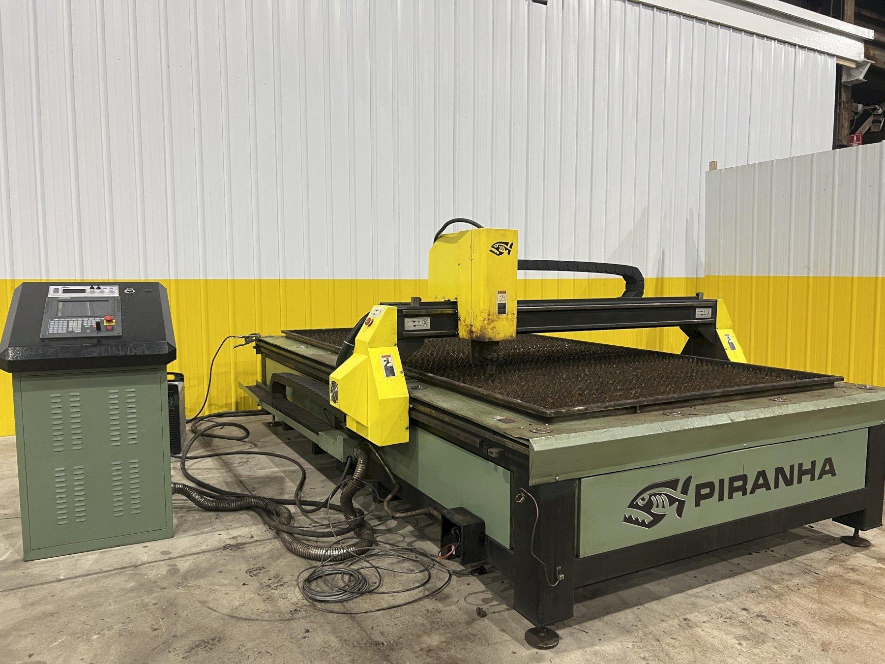
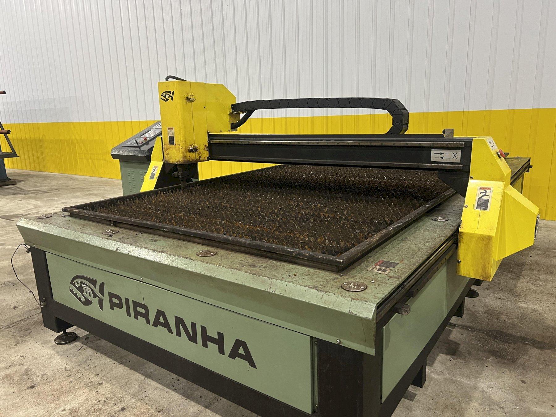
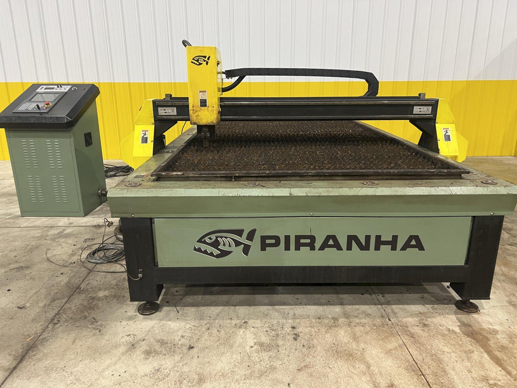
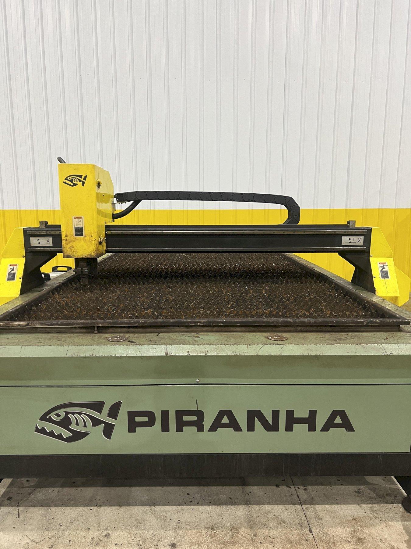
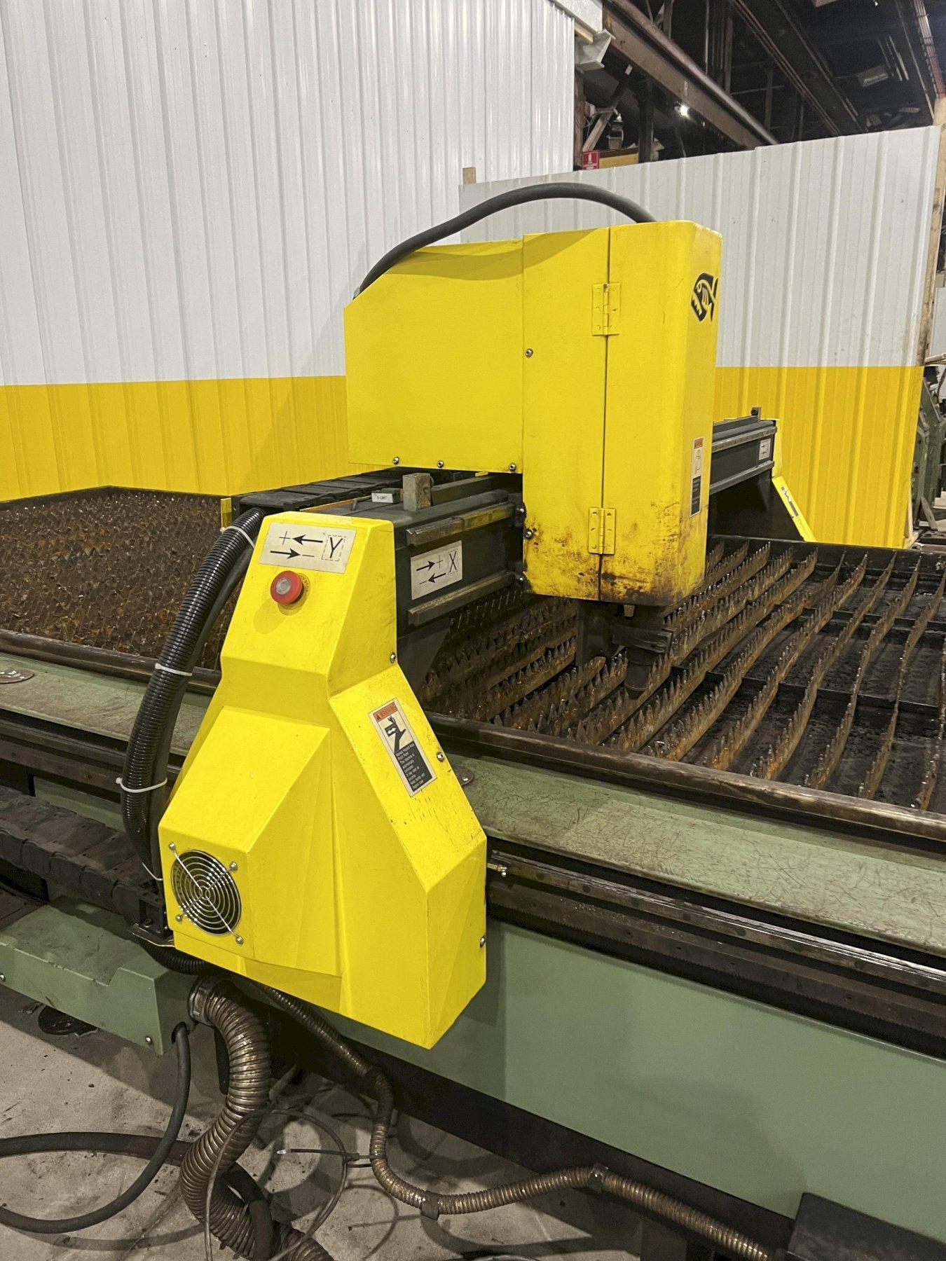
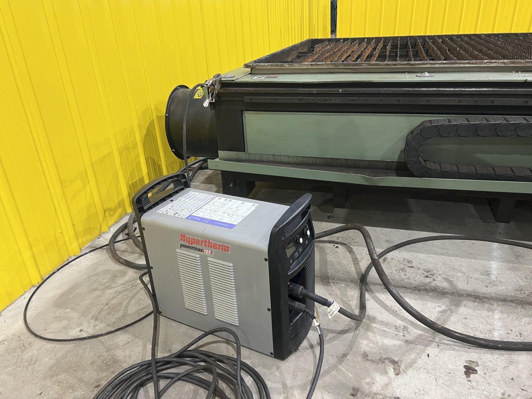
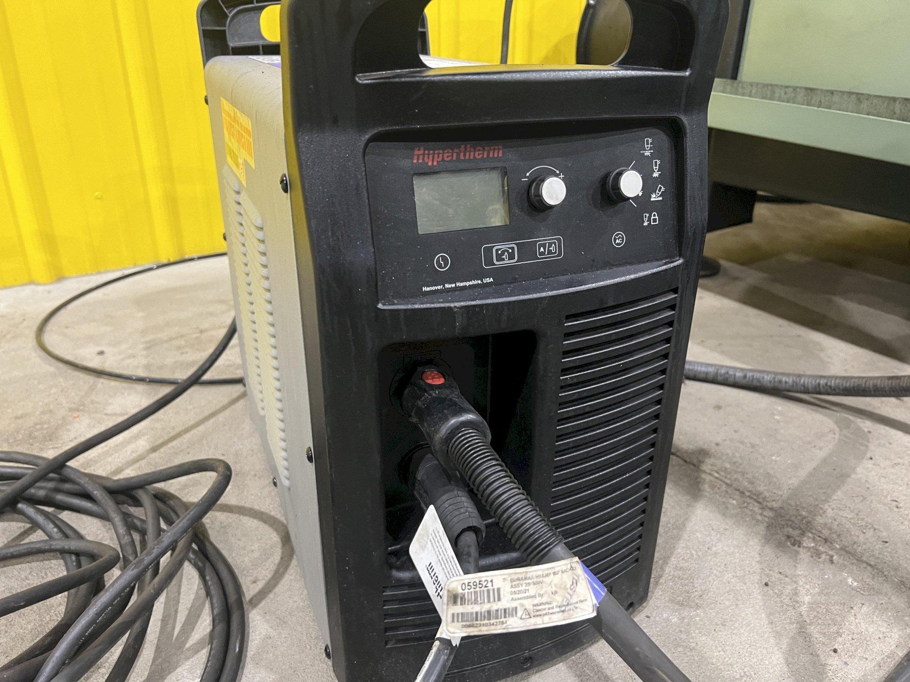
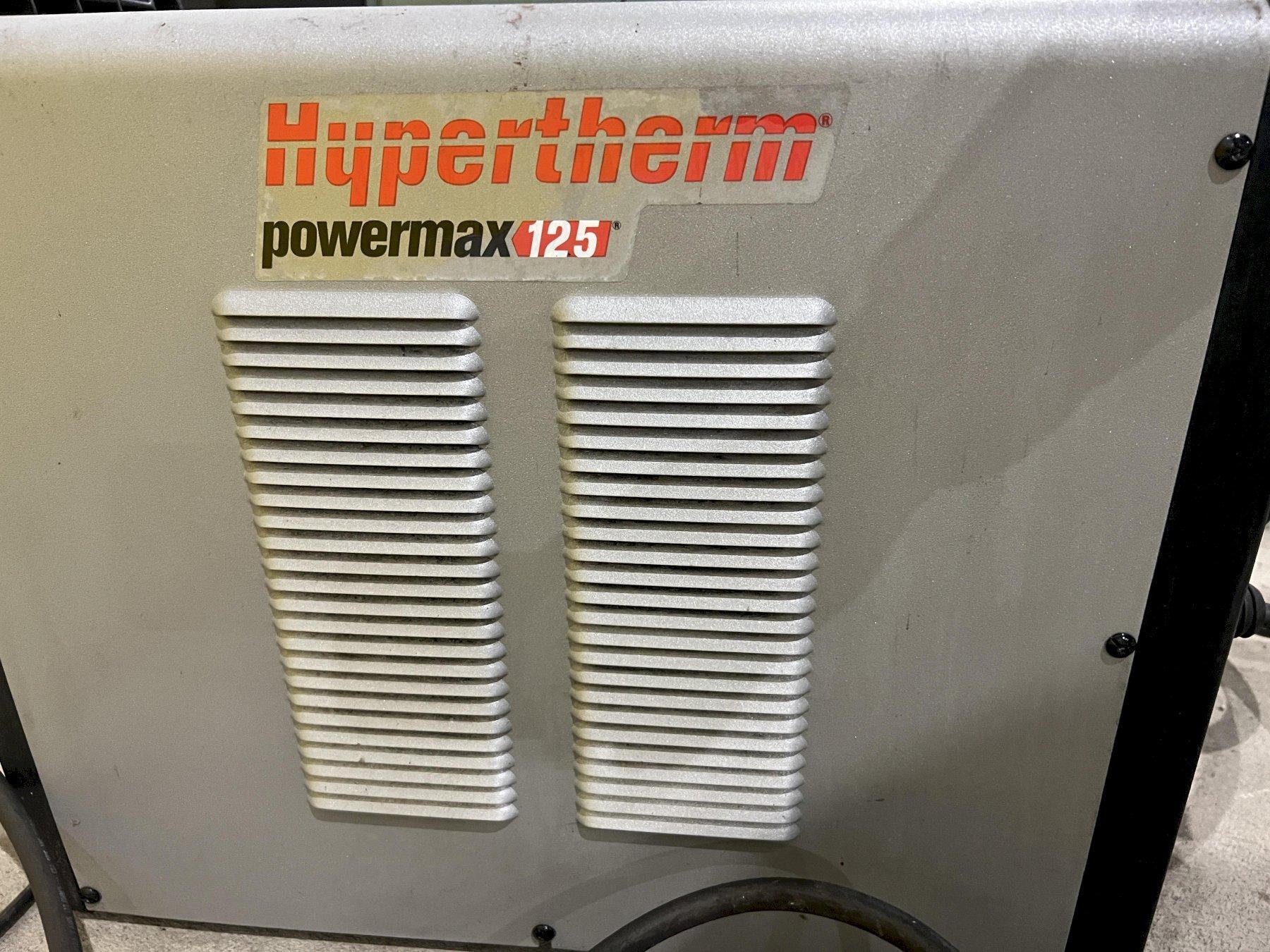
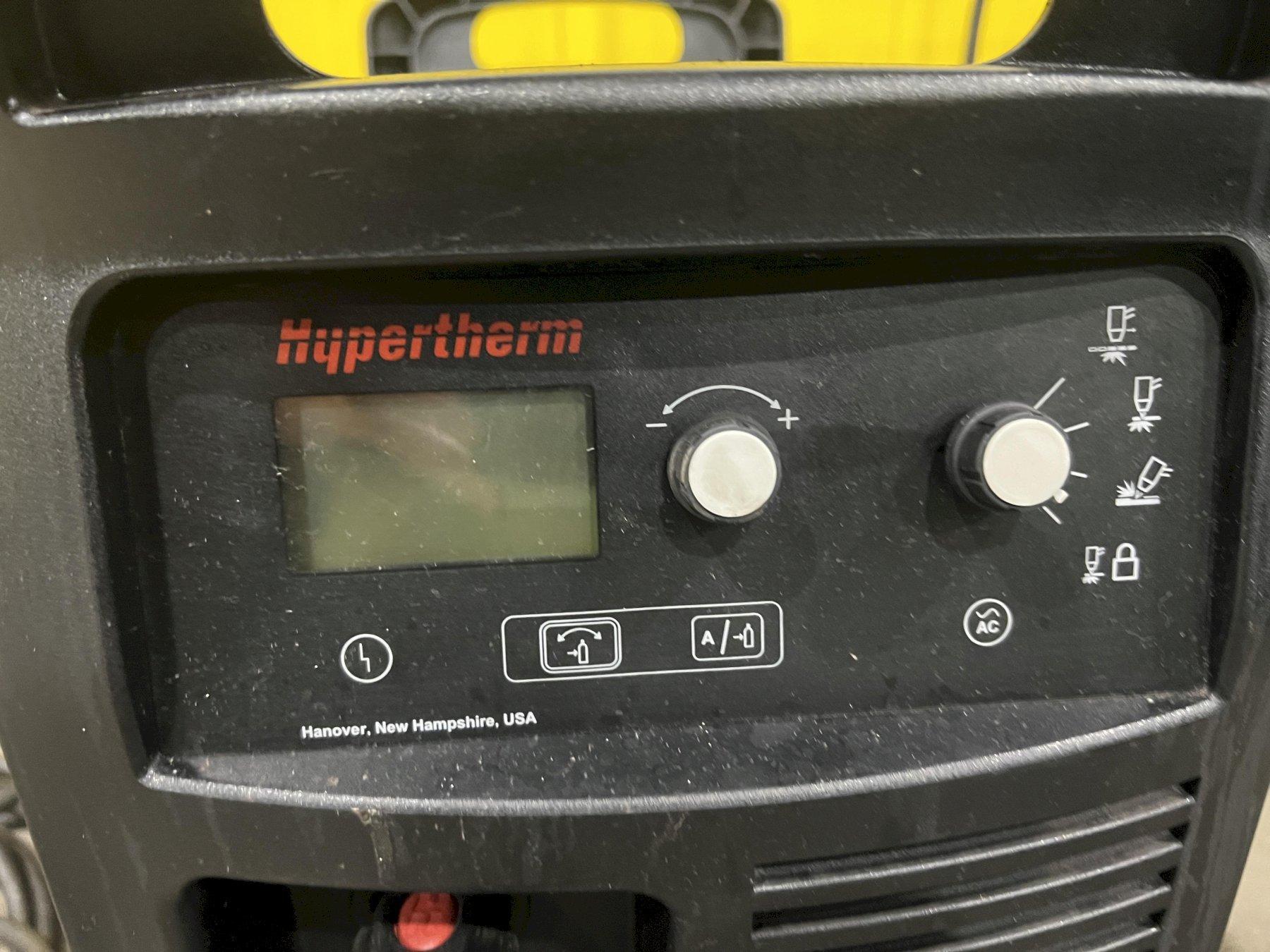
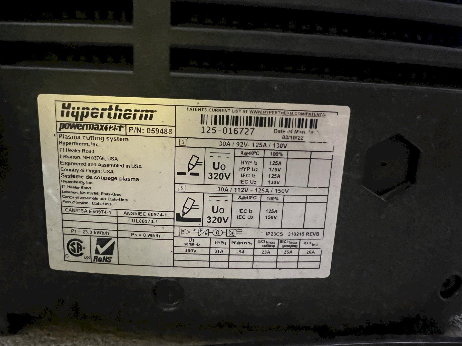
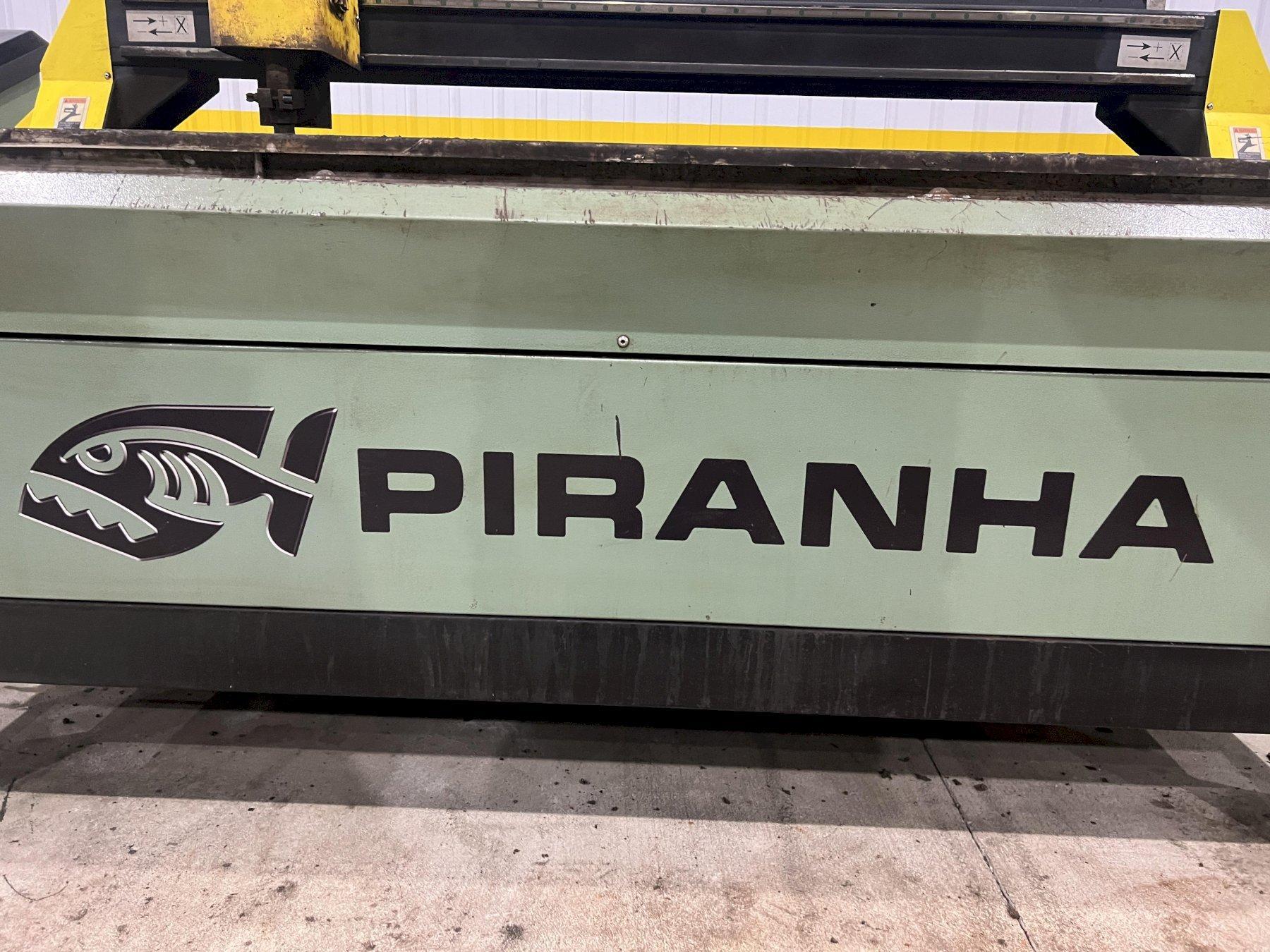
5' X 10' PIRANHA MODEL #C510 PLASMA TABLE SYSTEM HYPERTHERM POWERMAX 125: STOCK #20637
Stock
20637
Model
C510
Dealer Location
Ohio
Spec Sheet
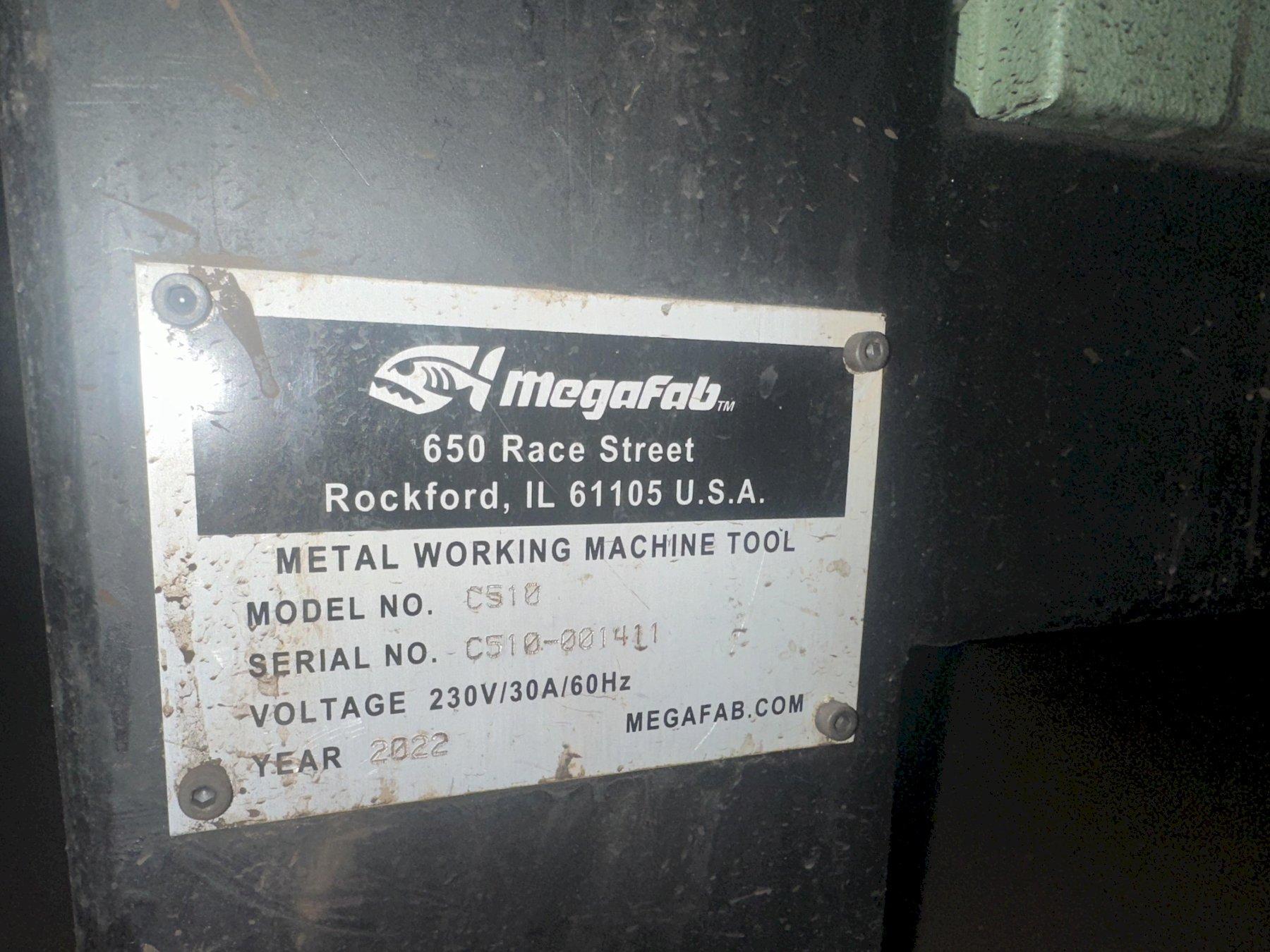
MODEL ...... C510
SERIAL ..... C510-001411
YEAR ....... 2022
Piranha C510 5′ x 10′ Plasma Table with Powermax 125 & Fast Cam Pro Software
STANDARD FEATURES
1. Rugged Construction – All-Welded Steel Frame (not bolt-together) with high accuracy linear guides and bearings. Machine is assembled complete at the factory
2. Dual Side Drive – gantry driven on both sides for maximum stability
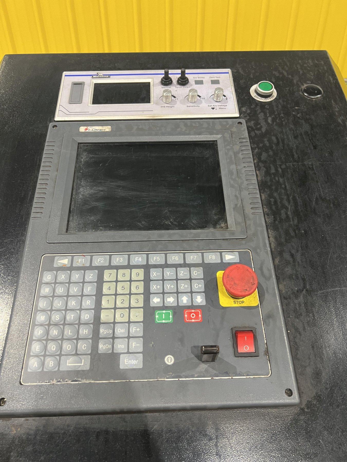
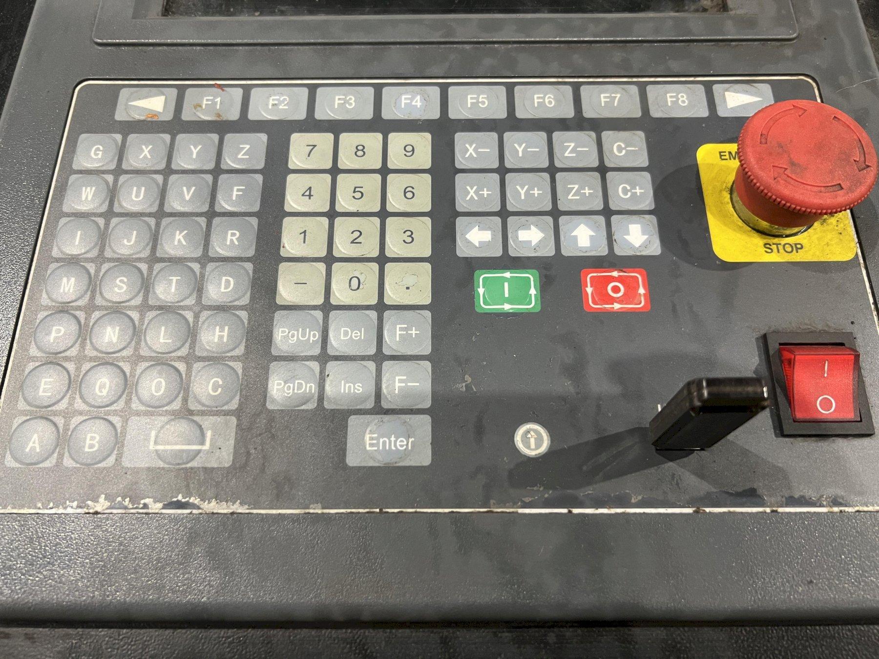
3. CNC Control with 10.4” High resolution color LCD monitor, shape library with 20 configurable shapes, 8MB memory & USB interface
4. Panasonic servo motors and drives – Powerful 400 watt servo motors (not stepper motors) on both X-axis and Y-axis with a maximum traverse speed of 8000mm/min.
5. Down draft exhaust system – Pre-vented duct work with exhaust fan for plasma dust extraction – no messy sludge to clean out and dispose of.
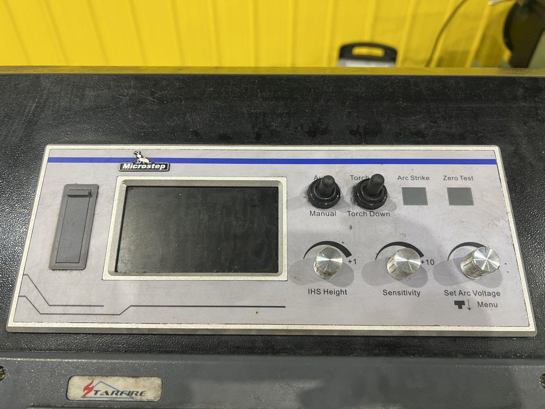
6. MicroStep Programmable Torch Height Control – controls torch height automatically
7. Breakaway Torch Mounting – protects the torch from inadvertent part tip-ups
8. FastCAM® Standard Programming System – DXF importing, editing and NC code generator.
| MACHINE SPECIFICATIONS FEATURE | SPECIFICATION |
| Maximum Rapid Speed | 393 IPM |
| CNC Control | Starfire |
| Frame and Bridge Construction | Weld Tubular Steel |
| Drive Motors | X-axis – Two Servo Motors Y-axis – Servo Motor Torch Height Control – Stepper Motor |
| Drive System | X-axis – Rack and Pinion each side Y-axis – Rack and Pinion Z-axis – Ball Screw |
| Torch Control | Arc Voltage with Initial Height Sensing |
| Torch Protection | Pneumatic Breakaway |
| Exhaust Fan | 1200 cfm @ 3” H2O |
| Powermax 85 MATERIAL THICKNESS | MAXIMUM CUTTING SPEED |
| 10 GA MS | 336 IPM |
| 1/4” MS | 164 IPM |
| 3/8” MS | 80 IPM |
| 1/2” MS | 48 IPM |
| 5/8” MS | 30 IPM |
| 3/4” MS | 24 IPM |
| FastCAM® Standard v Professional Feature | Description | Benefit | STD | PRO | ||||||
| Fully Integrated Drawing System | Create accurate 2D geometry in a fast and simple way using the inbuilt drawing editor. | No need for separate cost in buying and learning complicated CAD software. The FastCAM Editor is very easy to learn.
Draw -> Nest-> Cut from one system! |
X | X | ||||||
| CAD/DXF Compatability | DXF is the most common file format for transferring files between CAD & CAM Systems.
All FastCAM systems can import and export DXF files. |
CAD -> NC.
Fabricators are supplied job data in a variety of formats. To solve this problem, FastCAM can not only load a range of file types, it includes a suite of CAD smart tools for conversion to NC-ready code making the job input seamless and automatic. |
X | X | ||||||
| Bulk DXF import | Import multiple CAD drawings. | Increases job processing speed. | X | |||||||
| FastPATH™
Automatic Tool Pathing |
The software automatically analyzes nests, calculates cutting direction, kerf, entries/exits, sequencing, batch processing, hole avoidance and tabs. | Can eliminate 50% of programming time on tool pathing. All paths are reduced to a single mouse click. A substantial time and consumable saver, especially on complex nests and on a large number of cutouts. | X | |||||||
| Line Marking | Line marking is frequently used for marking the reference lines for subsequent operations such as bending, welding etc. Center points for drilling are also marked on the machine itself. | The purpose of marking on the cutting machine is to reduce cycle time and improve relative dimensional accuracy of various operations. | X | X | ||||||
| FastPLOT™ NC Visual Simulation | Easy editing and visual, graphic verification for CAM, DXF and NC code. You can visually check NC code for collisions or general behaviour, convert NC code to DXF, kerf offset NC code, plot NC code or nests for optical or documentation. | Minimizes risk on postprocessor by allowing checks on nests. Provides cutting time & distances and gross material utilization, making it ideal for costing and estimating individual parts or complete nests. Shows exactly what will happen when cutting. | X | X | ||||||
| Automatic Nesting | Nest into remnant or odd size plate. Full shape nesting compatible with all industry standards including DXF, IGES, NC, CAM, DSTV input and a large range of NC controls for output. | Optimizes the material usage and the sequence of cutting. | X | |||||||
| Common Cutting | Common cutting is used to cut a common side of two parts at the same time. | Can reduce the cutting and halve the piercing by joining two identical parts along a common straight boundary. | X | |||||||
No Video Available
Want to request a quote from the owner of this listing?
Request a QuoteFabricating Machines
- DUCT FORMERS & LINES
- EDGE TRIMMERS
- EDGERS
- EDGERS, STRIP, (Vertical & Trimmers)
- EDGING LINES
- FLAME CUTTING EQUIPMENT
- FLAME CUTTING EQUIPMENT, CNC
- FORMERS, METAL
- CUTTERS, BAR
- CUTTERS, FLAME
- CLICKERS
- COLD HEADERS
- CRADLES
- BENDING ROLLS
- CRUSHERS, (Steel Turnings & Chips)
- PLASMA CUTTERS
- RING FORMERS
- FABRICATING EQUIPMENT
- BURNING MACHINES
- FABRICATORS, CNC
- EDGE FORMING MACHINES
- RIM/RING EXPANDERS
- TRIMMERS, SHELL
- STRETCH FORMING MACHINES, EXTRUSION (Wrap) or SHEET (Plate)
- TRIMMING, BEADING & FLANGING MACHINES
- HEADERS, TRANSFER
- SHEET METAL FORMING MACHINERY
- SHEET STACKERS
- RIM/RING SHRINKERS
- COIL CLEANING LINES
- SHAPERS, PUNCH & FORM
- CUT-OFFS, PIPE, TUBE & BAR
- LEVELERS, TENSION
- HEADERS, SLUG
- SHEET LIFTERS
- SHEET METAL MACHINERY
- CUT-TO-LENGTH LINES
- UPSETTERS
- STRETCHERS / STRAIGHTENERS
- SHEET FEEDERS
- SHEET METAL MCHY, HAND OPERATED
- REACTORS, STEEL
- TORCHES
- TRIMMERS
- TRIMMERS, COLD BOLT
- TRIMMERS, EDGE
- TRIMMERS, STAMPING
- HEADERS, BALL
- HEADERS, COLD
- HEADERS, PROGRESSIVE DIE
- HEADERS, ROD
- HEADERS, ROLLER
- JEWELRY ROLLS
- NIBBLERS
- NOTCHING MACHINES
- NUT FORMERS
- RIM ROLLERS
- CUT-OFF LINES
- CUT-OFFS, PRESS TYPE
- CIRCLE & RING CUTTING MACHINES
- STRAINERS
- SHEET SLITTERS
- CUT-OFFS (Incl. Diamond Wheel)
- LEVELERS, ROLLER, PLATE, (Stretch)
- RING ROLLERS
- HEADERS, COLD, (Hollow Rivet)
- DIAMOND WHEEL CUT-OFF MACHINES
- FABRICATORS
- View All
Machine Brands
- MINSTER (185)
- HAAS (172)
- CINCINNATI (167)
- MAZAK (126)
- AMADA (119)
- BLANCHARD (115)
- OKUMA (105)
- GIDDINGS & LEWIS (92)
- DOOSAN (90)
- NIAGARA (77)
- LITTELL (76)
- LEBLOND (74)
- TRUMPF (66)
- BLISS (63)
- MORI SEIKI (63)
- BRIDGEPORT (60)
- CARLTON (58)
- American (56)
- CINCINNATI INC (56)
- YODER (55)
- WYSONG (54)
- DMG MORI (50)
- ARONSON (48)
- LANDIS (48)
- ROWE (46)
- IRM (43)
- TISHKEN (43)
- makino (43)
- PEDDINGHAUS (41)
- HEM (39)
- OKK (38)
- Lodge & Shipley (37)
- VERSON (37)
- DOALL (37)
- MONARCH (36)
- PACIFIC (36)
- SUMMIT (35)
- TOSHIBA (35)
- WATERBURY (34)
- Nilson (34)
- HYD-MECH (34)
- WAFIOS (33)
- HARDINGE (33)
- NATIONAL (33)
- YALE (33)
- BROWN & SHARPE (32)
- MITSUBISHI (32)
- FENN (31)
- BRADBURY (31)
- AIDA (29)
- CHEVALIER (29)
- OKAMOTO (29)
- HURCO (28)
- ACCURPRESS (28)
- LUBOW (27)
- TORRINGTON (27)
- COE (26)
- KOMATSU (26)
- WARNER & SWASEY (26)
- BULLARD (26)
- BUDGIT (26)
- AMERICAN STEEL LINE (25)
- FADAL (25)
- TOYODA (25)
- Clausing (25)
- Miller (25)
- FANUC (25)
- PANDJIRIS (25)
- POREBA (24)
- RMG (24)
- RUESCH (24)
- MARVEL (23)
- KURT (23)
- SHARP (23)
- ASC (23)
- HARTFORD (22)
- PINES (22)
- Hwacheon (21)
- TOS (21)
- Kent (19)
- FLOW (19)
- SHUSTER (19)
- FEDERAL (19)
- LYON (19)
- NAKASHIMADA (19)
- DALLAS (19)
- ROUSSELLE (19)
- EAGLE (19)
- Kitamura (18)
- BAIRD MACHINE (18)
- Jet (17)
- WHITNEY (17)
- HAVEN (17)
- RANSOME (16)
- BRUDERER (16)
- KEARNEY & TRECKER (16)
- DAKE (16)
- CINCINNATI BICKFORD (16)
- BERTSCH (16)
- BRADLEY (15)
- DEVLIEG (15)
- BUSHMAN (15)
- MICROCUT (15)
- B & K (15)
- HEIM (15)
- BROTHER (15)
- STANAT (15)
- PIRANHA (14)
- Sunnen (14)
- CINCINNATI MILACRON (14)
- JOHNFORD (14)
- LEWIS (14)
- CLEEREMAN (14)
- KALAMAZOO (14)
- LINCOLN (14)
- WATERBURY FARREL (14)
- CWP (13)
- TSUGAMI (13)
- MIGHTY VIPER (13)
- MITUTOYO (13)
- WEBB (13)
- BYSTRONIC (13)
- NATIONAL MACHINERY (13)
- KAESER (13)
- LUCAS (13)
- AJAX (13)
- U.S. BAIRD (13)
- EATON LEONARD (13)
- WOTAN (12)
- MESSER (12)
- Awea (12)
- DREIS & KRUMP (12)
- PERFECTO (12)
- MATTISON (12)
- TIMESAVERS (12)
- LEADWELL (12)
- Ingersoll-Rand (12)
- HYSTER (12)
- SAMSUNG (12)
- PORTAGE (12)
- PULLMAX (12)
- LAMINA (12)
- EITEL (12)
- GARDNER DENVER (12)
- LVD (12)
- GROB (11)
- STANDARD (11)
- UNION (11)
- DURANT (11)
- W.F. Wells (11)
- CLAUSING COLCHESTER (11)
- HTC (11)
- Gorbel (11)
- FASTENER ENGINEERS (11)
- THOMPSON (11)
- HANKOOK (11)
- ELECTROWELD (11)
- Scotchman (11)
- ARDCOR (11)
- AIRAM (11)
- SPRINGFIELD (11)
- DAEWOO (11)
- NORTON (11)
- Wheelabrator (11)
- LNS (11)
- YOU JI (10)
- RED BUD (10)
- SNK (10)
- COLT (10)
- OLIVER (10)
- FEED LEASE (10)
- ROUNDO (10)
- MOORE (10)
- ROFIN (10)
- YCM (10)
- STANLEY VIDMAR (10)
- Dainichi (10)
- HNK (10)
- P & H (10)
- BIRMINGHAM (10)
- DAHLSTROM (10)
- Tennant (10)
- WELLS (9)
- PRESTO (9)
- Edwards (9)
- CINCINNATI GILBERT (9)
- IOWA PRECISION (9)
- LEBLOND REGAL (9)
- DENISON (9)
- MATSUURA (9)
- DILLON (9)
- VICTOR (9)
- BLOW (9)
- STERLING (9)
- TOLEDO (9)
- LINCOLN ELECTRIC (9)
- BEHRINGER (9)
- ADIRA (9)
- Hexagon (9)
- DAYTON (9)
- L & J (9)
- PERKINS (9)
- MODERN (9)
- GARY (9)
- INGERSOLL (9)
- KASTO (9)
- GEKA (9)
- ZEISS (9)
- AMERICAN INDUSTRIAL (9)
- DURMA (9)
- COOPER WEYMOUTH PETERSON (9)
- SOUTHWORTH (9)
- STRECKER (9)
- ALPHA (9)
- TRU TURN (9)
- Walker (9)
- HYUNDAI WIA (9)
- EGAN (9)
- CITIZEN (9)
- ACME (8)
- VAUGHN (8)
- GENERAL ELECTRIC (8)
- PEERLESS (8)
- HARRINGTON (8)
- CHICAGO DREIS & KRUMP (8)
- Chicago (8)
- DIACRO (8)
- COOPER WEYMOUTH (8)
- LOOPCO (8)
- STAMCO (8)
- ROMI (8)
- Multicam (8)
- KURAKI (8)
- MITTS & MERRILL (8)
- MILLTRONICS (8)
- Powermatic (8)
- OMAX (8)
- American Pacemaker (8)
- DAITO (8)
- MUBEA (8)
- Enco (8)
- STAR (8)
- Machitech (8)
- YAMA SEIKI (8)
- AUTOMATED PACKAGING SYSTEMS (8)
- ALLSTEEL (8)
- Prima (8)
- SIEMENS (8)
- LEHMANN (8)
- Ficom (8)
- PRATT & WHITNEY (8)
- KONE (7)
- MCKAY (7)
- CALDWELL (7)
- PAXSON (7)
- STRIPPIT (7)
- Axelson (7)
- FICEP (7)
- Thermwood (7)
- ENGEL (7)
- IEMCA (7)
- CASTEX (7)
- STANDARD MACHINERY (7)
- HAMMOND (7)
- GF AgieCharmilles (7)
- MITSUI SEIKI (7)
- KOIKE ARONSON (7)
- KNUTH (7)
- TORNOS (7)
- ACER (7)
- BARBER COLMAN (7)
- VESTIL (7)
- Delta (7)
- WILTON (7)
- ACRA (7)
- CHARMILLES (7)
- RAPID AIR (7)
- HYDMECH (7)
- HEALD (7)
- RIDGID (6)
- AMD (6)
- WENZEL (6)
- CLEARING (6)
- GREENERD (6)
- NEW HOLLAND (6)
- HANNIFIN (6)
- JACO (6)
- HARIG (6)
- FEDERAL PACIFIC (6)
- ANGOR (6)
- COSEN (6)
- GSW (6)
- MICRO PRODUCTS (6)
- BHS TORIN (6)
- ROTARY (6)
- Nomura (6)
- SQUARE D (6)
- SELCO (6)
- SPARK (6)
- CONTROLLED AUTOMATION (6)
- NARDINI (6)
- GROEN (6)
- STAMTEC (6)
- GLEASON (6)
- P&H (6)
- MURATEC (6)
- MAAG (6)
- CLEARING NIAGARA (6)
- SYSTEM TECHNOLOGIES (6)
- REID (6)
- SHIGIYA (6)
- Starrett (6)
- VOORTMAN (6)
- AWS (6)
- KELLENBERGER (6)
- LOCKFORMER (6)
- WORTHINGTON (6)
- JACOBS (6)
- HEY (6)
- AWC (6)
- ABBEY ETNA (6)
- JLG (6)
- KING (6)
- AMERICAN INDUCTION (6)
- T-DRILL (6)
- CRAVEN (6)
- WARREN INDUSTRIES (6)
- CLEVELAND (6)
- BETTER ENGINEERING (6)
- TOYOKOKI (6)
- SOUTH BEND (6)
- WALDRICH (6)
- CHIRON (6)
- ERWTech/UCG (6)
- Taylor Winfield (6)
- SALVAGNINI (6)
- WELDWIRE (6)
- DEHOFF (6)
- WELE (6)
- ROURA (6)
- PANGBORN (6)
- OMCG (5)
- PARPAS (5)
- MEECO (5)
- G & L (5)
- RAS (5)
- Jones & Lamson (5)
- CONTROLLED POWER (5)
- MANFORD (5)
- TELEDYNE READCO (5)
- VANGUARD (5)
- DAVI (5)
- SKODA (5)
- Pat Mooney (5)
- NAKAMURA TOME (5)
- OTO MILLS (5)
- ELDORADO (5)
- EXTRUDE HONE (5)
- BINNS & BERRY (5)
- Rollomatic (5)
- CUSHMAN (5)
- BARRETT (5)
- KINEFAC (5)
- DAVENPORT (5)
- TARUS (5)
- DEMAG (5)
- SUPERMAX (5)
- GRIZZLY (5)
- ATLAS COPCO (5)
- GREENARD (5)
- SAFAN (5)
- LISSMAC (5)
- BRIDGEPORT ROMI (5)
- PATTERSON-KELLEY (5)
- OILGEAR (5)
- PEDRICK (5)
- ATLANTIC (5)
- CATERPILLAR (5)
- MITCHELL (5)
- CORSTEEL (5)
- BLM ADIGE (5)
- Supertec (5)
- AJAX TOCCO (5)
- ROCKFORD (5)
- BROWN & BOGGS (5)
- MECON (5)
- FARREL (5)
- C & M (5)
- ALVA ALLEN (5)
- OKUMA & HOWA (5)
- DANLY (5)
- NILES (5)
- LANSING (5)
- Pullmax Ursviken (5)
- Unknown (5)
- JONES & SHIPMAN (5)
- SHIBAURA (5)
- SIGNODE (5)
- Roper Whitney (5)
- KOMATSU NTC (5)
- ACCURSHEAR (5)
- FELLOWS (5)
- SOCO (5)
- NOBLES (5)
- AEM (5)
- WILSON (4)
- AUTOQUIP (4)
- SUTTON (4)
- ANDERSON COOK (4)
- GENIE (4)
- COFFING (4)
- DETROIT (4)
- TIMESAVER (4)
- HUSKY (4)
- NAKAMURA-TOME (4)
- JAYBIRD (4)
- REX (4)
- TIMEMASTER (4)
- BLUE M (4)
- MSC (4)
- ESAB (4)
- GLEBAR (4)
- Colombo (4)
- AUTOMATIC FEED (4)
- TESKER (4)
- Ermak (4)
- SORGEL (4)
- PEXTO (4)
- RODGERS (4)
- BETTS (4)
- FRORIEP (4)
- MIDACO (4)
- ROYAL (4)
- TUREK & HELLER (4)
- PROGRESSIVE (4)
- ACCO WRIGHT (4)
- SYNTRON (4)
- COILMATE (4)
- SPEEDAIRE (4)
- US INDUSTRIAL (4)
- EUROMAC (4)
- HERR VOSS (4)
- ROTAB (4)
- SAYLOR-BEALL (4)
- GRANITE (4)
- NILFISK ADVANCE (4)
- WALL COLMUNOY (4)
- MANVILLE (4)
- NISSAN (4)
- WARD (4)
- DEA (4)
- GEMINIS (4)
- DYNAMIC AIR (4)
- MEUSER (4)
- RELIANCE (4)
- DeWalt (4)
- WELTY WAY (4)
- ZOLLER (4)
- JMT (4)
- KINGSTON (4)
- HYUNDAI KIA (4)
- SEYI (4)
- IMCAR (4)
- MICRO WELD (4)
- FOMIndustrie (4)
- HITACHI SEIKI (4)
- IKEDA (4)
- TORIN (4)
- STANKO (4)
- Breton (4)
- Ingersoll Rand (4)
- SUNDSTRAND (4)
- BETENBENDER (4)
- SESCO (4)
- ROYAL MASTER (4)
- COMPAIR (4)
- SMTCL (4)
- REGAL (4)
- ROUSELLE PRESS (4)
- Haco Atlantic (4)
- Sheffield (4)
- ERIE (4)
- LYNDEX NIKKEN (4)
- STUDER (4)
- GRAY (4)
- ACCO (4)
- NEFF (4)
- CHS AUTOMATION (4)
- ALMCO (4)
- KONECRANES (4)
- THERMAL DYNAMICS (4)
- HONOR SEIKI (4)
- CHAMBERSBURG (4)
- COLLIS (4)
- QUINCY (4)
- Haco (4)
- Medart (4)
- PIQUA (4)
- SIRCO (4)
- PA INDUSTRIES (4)
- BOYAR SCHULTZ (4)
- PRAB (4)
- ENERPAC (4)
- DMG MORI SEIKI (4)
- MURATA (4)
- SHELDON (4)
- SIDNEY (4)
- SCHIESS (4)
- MITSUBISHI EDM (4)
- CM LODESTAR (4)
- HASENCLEVER (4)
- ROTO-FINISH (4)
- MIDWEST (4)
- HK (4)
- SOLBERGA (4)
- Grand Rapids (4)
- HARDINGE-BRIDGEPORT (4)
- MAREN (4)
- BECKWOOD (4)
- RAHN (4)
- LAKE ERIE (4)
- D.C. MORRISON (4)
- LEISTRITZ (4)
- SETCO (4)
- ALPHIL (4)
- Penn (4)
- Accupress (3)
- SCHENCK (3)
- ROSS (3)
- JETLINE (3)
- EXCELLO (3)
- 3D SYSTEMS (3)
- ATLAS (3)
- OLSUN (3)
- VARIAN (3)
- STRACHAN (3)
- BOBCAT (3)
- FORTE (3)
- REED (3)
- STEEL STORAGE SYSTEMS (3)
- HAMILTON (3)
- Hansford (3)
- YUASA (3)
- FULLER (3)
- RUSH (3)
- ADVANCE CUTTING SYSTEMS (3)
- FORTUNE (3)
- Pearson (3)
- WELLSAW (3)
- OGP (3)
- TECO (3)
- FUKUI (3)
- MEPACO (3)
- MACBEE (3)
- ABSOLENT (3)
- TAFT PIERCE (3)
- LIBERTY (3)
- TARNOW (3)
- EATON (3)
- P/A (3)
- ERCOLINA (3)
- Westward (3)
- CINCINNATI MACHINES (3)
- BOSCH SURFTRAN (3)
- Snorkel (3)
- Fanuc Robodrill (3)
- SMTW (3)
- Biesse (3)
- WHITING (3)
- WRIGHT (3)
- Warren (3)
- COMACA (3)
- MIYANO (3)
- OSTER (3)
- STONE (3)
- PERFECT (3)
- CYRIL BATH (3)
- MITSUBISHI ELECTRIC (3)
- HERKULES (3)
- SOUTH BEND JOHNSON (3)
- LORS (3)
- TRIAD (3)
- Lehigh (3)
- ASQUITH (3)
- Onsrud (3)
- MOTOMAN (3)
- LANTECH (3)
- FEELER (3)
- CLARK (3)
- CAT (3)
- TACCHI (3)
- MICHIGAN ROLL FORM (3)
- CONE (3)
- SERTOM (3)
- SUTHERLAND (3)
- Ford (3)
- T.J. SNOW (3)
- Ibarmia (3)
- MANSAVER (3)
- SNOW (3)
- BURRMASTER (3)
- PENTALIFT (3)
- KANE & ROACH (3)
- SODICK (3)
- Hypertherm (3)
- DREISTERN (3)
- GISHOLT (3)
- Troyke (3)
- PRECISION GRANITE (3)
- HITACHI (3)
- ZEKS (3)
- HYDROMAT (3)
- FIM (3)
- DORRIES (3)
- HUCK (3)
- POLAMCO (3)
- PATTERSON (3)
- PARKER MAJESTIC (3)
- FRYER (3)
- Tennsmith (3)
- PARKER (3)
- SCHARMANN (3)
- LAGUN (3)
- HI VAC (3)
- Kentex (3)
- ECONOMY (3)
- LANDA (3)
- VECTRAX (3)
- MINUTEMAN (3)
- HARRISON (3)
- TRI TOOL (3)
- T & H (3)
- MICHIGAN (3)
- ENVIRO-PAK (3)
- SPITFIRE (3)
- MACHINE CONCEPTS (3)
- TAYLOR (3)
- Rockwell (3)
- TRACKMOBILE (3)
- Ermaksan (3)
- STEELMASTER (3)
- FARO (3)
- RICHARDS (3)
- SULLAIR (3)
- SWECO (3)
- AUTO-SERT (3)
- LEROI (3)
- HAEGER (3)
- O-M Ltd (3)
- PRESS ROOM EQUIPMENT (3)
- Fanamation (3)
- Kia (3)
- DTI (3)
- EVERETT (3)
- L&J (3)
- Keyence (3)
- GARDNER (3)
- DAVIS (3)
- MARKFORGED (3)
- FRANKLIN (3)
- Femco (3)
- SANDVIK (3)
- NSK (3)
- Conair (3)
- BISON (3)
- HELLER GROUP (3)
- KEARNS & RICHARDS (3)
- EUMUCO (3)
- MSI (3)
- PYTHON (3)
- CROWN (3)
- BETARAM (3)
- VOLLMER (3)
- CARLO SALVI (3)
- HYUNDAI-WIA (3)
- HE&M (3)
- LEWCO (3)
- Philadelphia Tramrail (3)
- CRAFTSMAN (3)
- CP MFG (3)
- WEST BEND (3)
- BCP (3)
- MITSUI (3)
- NIKKEN (3)
- GOFF (3)
- ASAHI OKUMA (3)
- TECHNIDRILL (3)
- ROHM (3)
- FAMCO (3)
- MACRODYNE (3)
- AIR FEED INC. (3)
- COILMATIC (3)
- TRENNJAEGER (3)
- SAMCO (3)
- BRIDGEPORT HARIG (3)
- ACORN (3)
- MTD (3)
- CECO (3)
- CULLEN FRIESTEDT (3)
- PEMSERTER (3)
- FABRILINE (3)
- SLM (3)
- BUFFALO (3)
- HTC HYDRA-TOOL (3)
- SPARTAN (3)
- APPLIED RECOVERY SYSTEMS (3)
- AKS (3)
- TSUDAKOMA (3)
- BERTHIEZ (3)
- MILWAUKEE (3)
- Lista (3)
- Vantage (3)
- JENNINGS (3)
- Eurotech (3)
- FOSDICK (3)
- FUTURMILL (3)
- METLSAW (3)
- AXYZ (3)
- TANAKA (3)
- Kiwa (2)
- SCHNELL (2)
- CUSTOM (2)
- Ernst (2)
- CLIMAX (2)
- ULINE (2)
- Ryazan (2)
- ZERO (2)
- BERTOLETTE (2)
- WJM (2)
- HARMONY (2)
- ORII (2)
- TOYOTA (2)
- WMW (2)
- Standard Resistance (2)
- Voss (2)
- PHOENIX (2)
- TAKISAWA (2)
- ELDORADO MEGA (2)
- HANSVEDT (2)
- KEINS (2)
- HERON (2)
- WYSONG & MILES (2)
- GODFREY & WING (2)
- WESTINGHOUSE (2)
- IKEGAI (2)
- ASAHI SUNAC (2)
- CHIYODA (2)
- HUESTIS (2)
- ACCRA WIRE (2)
- GIORIA (2)
- CONTRX (2)
- FPT (2)
- QPAC (2)
- MTC (2)
- Lindberg (2)
- nLight (2)
- MARATHON (2)
- MORONI (2)
- 3M (2)
- BISHAMON (2)
- DUNNAGE (2)
- CAMaster (2)
- DEDTRU (2)
- HANWHA (2)
- TANNEWITZ (2)
- KUNDEL (2)
- MANCHESTER (2)
- WESTBROOK (2)
- POWERTRAN (2)
- SIHI (2)
- HILL-ACME (2)
- NORDSON (2)
- TUDA (2)
- METTLER-TOLEDO (2)
- DUST CONTROL (2)
- CAMPBELL HAUSFELD (2)
- MIIC (2)
- PRECISION (2)
- Carnaghi (2)
- BRANER (2)
- V & O (2)
- PUTNAM (2)
- QUASER (2)
- NIIGATA (2)
- FRONIUS (2)
- SAVAGE (2)
- ROFIN LASAG (2)
- LOAD LIFTER (2)
- VULCAN (2)
- NAGEL (2)
- Swistek (2)
- WAUSEON (2)
- MONTGOMERY (2)
- DRAFTO (2)
- ALLIANT (2)
- WAGNER (2)
- NSS (2)
- HEINRICH MULLER (2)
- KOCH (2)
- Waldrich Coburg (2)
- POWER TEAM (2)
- SCHENKER (2)
- West Michigan Spline (2)
- Raymond (2)
- Dodge (2)
- BAYKAL (2)
- DYNAMIC FEEDS (2)
- ELUMATEC (2)
- TITAN (2)
- MEDINA (2)
- Shop Sabre (2)
- O-M (2)
- SHAW BOX (2)
- STAHL CRANE SYSTEMS (2)
- WOHLENBERG (2)
- Barnes (2)
- NORWALK (2)
- SCHUNK (2)
- Gidding & Lewis (2)
- HPM (2)
- MTE (2)
- HELLER (2)
- DIMECO ALIPRESSE (2)
- Wiedemann (2)
- PALATEK (2)
- UNIVERSAL (2)
- Grieve (2)
- HOBART (2)
- AMERICAN HOFMANN (2)
- KALAMAZOO STARTRITE (2)
- GE SCHMIDT (2)
- HEAT SEAL (2)
- OTW (2)
- WALLACE COAST (2)
- HOMMA (2)
- GLEASON PFAUTER (2)
- GRUENDLER (2)
- NUGIER (2)
- Vidmar (2)
- WALTHER TROWAL (2)
- Walter (2)
- Berco (2)
- US MACHINE (2)
- RANSOHOFF (2)
- GOULD & EBERHARDT (2)
- ARC SPECIALTIES (2)
- Kohler (2)
- LK (2)
- CBG TECHNOLOGIES (2)
- CLAUSING KONDIA (2)
- ADVANTAGE (2)
- NICHOLS (2)
- FARR (2)
- W.A. WHITNEY (2)
- BOSCHERT (2)
- MIGHTY TURN (2)
- MILLUTENSIL (2)
- EASTEY (2)
- FIOA (2)
- RAFTER (2)
- AMET (2)
- SCHMIDT (2)
- Nukon (2)
- MOLINE (2)
- CMS (2)
- THERN (2)
- STARTRITE (2)
- MTI (2)
- WATSON STILLMAN (2)
- Standard Modern (2)
- YOUGAR (2)
- PAMA (2)
- Masterwood (2)
- Accurl (2)
- HEVI DUTY (2)
- WILKERSON (2)
- HURRICANE (2)
- PRODUCTO (2)
- APT (2)
- AARON PROCESS EQUIPMENT (2)
- COUTH (2)
- N/A (2)
- Pressta (2)
- FENN / BHS (2)
- Thermatool (2)
- Do All (2)
- BUHLER (2)
- CLAUSING METOSA (2)
- Elgin (2)
- WAUKESHA (2)
- EIMELDINGEN (2)
- HOCKMEYER (2)
- TRAUB (2)
- STEWART WARNER (2)
- 2 Mitsubishi (2)
- MORSE (2)
- HANDTMANN (2)
- Car-Anth (2)
- TECHNIKS (2)
- PROTH (2)
- PHASE II (2)
- KASHIFUJI (2)
- Leitz (2)
- APEX (2)
- ROSLER (2)
- METAL MUNCHER (2)
- Jammes (2)
- PROCECO (2)
- Wean (2)
- LANGELIER (2)
- Kurtz Ersa (2)
- AMERICAN STEEL (2)
- WHITE (2)
- MAGNUS (2)
- Adige BLM (2)
- RBI (2)
- BRONX (2)
- Technica (2)
- TOSHIBA SHIBAURA (2)
- SOUTHWESTERN INDUSTRIES (2)
- Apec (2)
- DMC (2)
- INNOCENTI (2)
- GIDDINGS & LEWIS FRASER (2)
- DAKE JOHNSON (2)
- DONALDSON (2)
- NORTH AMERICAN (2)
- OOYA (2)
- DOOSAN DAEWOO (2)
- SCHIESS FRORIEP (2)
- PETERBUILT (2)
- ALLEGHENY (2)
- Omniturn (2)
- AGIE (2)
- WILLIS (2)
- OCTAGON (2)
- JOTES (2)
- TSCHUDIN (2)
- TAI PIIN (2)
- Benchmaster (2)
- WEILER (2)
- VDF (2)
- Park Industries (2)
- ASHLAND (2)
- GREENLEE (2)
- STERTIL KONI (2)
- TORIT (2)
- ALPINE (2)
- JUNKER (2)
- OSBORN (2)
- COBALT (2)
- HAEUSLER (2)
- ALPHA/THERMATOOL (2)
- K.O. LEE (2)
- Pro Steel (2)
- Sunfirm (2)
- FELDMAN (2)
- MOSSBERG (2)
- WILLIAMS & WHITE (2)
- WOLF (2)
- WF Wells (2)
- ATS (2)
- Shars (2)
- OMEGA (2)
- Forest-Line (2)
- JET EDGE (2)
- AEF (2)
- SAFOP (2)
- LIVONIA MAGNETICS (2)
- FRIGGI (2)
- KYOEI (2)
- BAC (2)
- LIEBHERR (2)
- APPLETON (2)
- Kan (2)
- SINTOBRATOR (2)
- WALLACE (2)
- U.S. INDUSTRIAL (2)
- MICHIGAN ROTOFLOW (2)
- TRAK (SOUTHWESTERN INDUSTRIES) (2)
- BAY CAST (2)
- BOWERS (2)
- Hoan (2)
- Hofler (2)
- TRU-TURN (2)
- V&O (2)
- Aerzen (2)
- New Century (2)
- BLUE VALLEY (2)
- HGG (2)
- ASL (2)
- RADYNE (2)
- OCAP (2)
- ROY (2)
- ADVANCED (2)
- CONCO (2)
- MORSE CUTTING TOOLS (2)
- Whirlwind (2)
- PREMIER (2)
- S&T DYNAMICS (2)
- Linde (2)
- LOWN (2)
- Grove (2)
- Sellers (2)
- SMART (2)
- SPEEDFAM (2)
- MURATA WIEDEMANN (2)
- KELLER (2)
- CENTRAL MACHINERY (2)
- KAFO (2)
- AIR TECHNICAL INDUSTRIES (2)
- CLINTON (2)
- RUF (2)
- Kinetic (2)
- BRYANT (2)
- HANKISON (2)
- Falk (2)
- ECOTECH (2)
- ARMSTRONG (2)
- CAMPBELL (2)
- Trion (2)
- PERMADUR (2)
- CADY LIFTERS (2)
- CLOOS (2)
- Weingartner (2)
- ROBBINS & MYERS (2)
- Nabertherm (2)
- WEBSTER & BENNETT (2)
- GULLCO (2)
- ENVIROTRONICS (2)
- SACK & KIESSELBACH (2)
- HERCULES AJAX (2)
- DMG (2)
- BINZEL (2)
- HP (2)
- MULTIPRESS (2)
- ARKU (2)
- DARLEY (2)
- UCG (2)
- BURR OAK (2)
- MAYFRAN (2)
- H.H. ROBERTS (2)
- GMC (2)
- Loewer (2)
- LVD Strippit (2)
- GURUTZPE (2)
- HENRI LINE (2)
- Digi (2)
- BEATTY (2)
- RAMPE (2)
- Leblond Makino (2)
- Standard Industrial (2)
- Dener (2)
- PILLAR (2)
- STRILICH (2)
- ALORIS (2)
- SMC (2)
- GROTNES (2)
- GIANT (2)
- PRECISION INDUSTRIES (2)
- PANASONIC (2)
- RAMCO SANDERS (2)
- SWEED (2)
- TECNA (2)
- MICRO AIR (2)
- CARSON ENGINEERING (2)
- WISCONSIN (2)
- RMT (1)
- ENSHU (1)
- GUIFIL (1)
- Dreher (1)
- POLAND (1)
- HAUTAU (1)
- MATTHEWS (1)
- INTERSOURCE (1)
- Ecoa (1)
- LEXAIR (1)
- ADDISON-MCKEE (1)
- BOURN & KOCH (1)
- RAPID MACHINERY (1)
- PRESTON EASTIN (1)
- GMS (1)
- Logeman (1)
- FIVES CINETIC (1)
- BestFlex / FMH (1)
- HTF (1)
- Arc Industries (1)
- CNC Factory (1)
- HARDINGE QUEST (1)
- MILLPORT (1)
- DOUGLAS (1)
- VISION WIDE (1)
- SILENT HOIST (1)
- HURST (1)
- Lee Industries (1)
- KABAR (1)
- ABB (1)
- Leonard Tube Master (1)
- SCHRODER (1)
- VIRTEK (1)
- Roll-In (1)
- ASEA (1)
- CHS (1)
- MAR-BEL (1)
- HENDEY (1)
- COIL HANDLING SYSTEMS (1)
- MAIR RESEARCH (1)
- REIS (1)
- OGDEN (1)
- BARDONS & OLIVER (1)
- TCM (1)
- RIFA (1)
- Sumitomo (1)
- KASUGA (1)
- SOUTHWEST (1)
- Advanced Recycling Systems (1)
- Ribon (1)
- Unified Surface Solutions (1)
- SPANG (1)
- SIP (1)
- Metro (1)
- EPCO (1)
- Indusco-Kaev (1)
- STREET (1)
- CONCOA (1)
- LISCIANI (1)
- RADIUS (1)
- COLLINS MICROFLAT (1)
- TRIANGLE (1)
- Constellation (1)
- ALCECO (1)
- VAC-U-MAX (1)
- CINCINNATI MILACRON HEALD (1)
- CRIZAF (1)
- INDUCTOHEAT (1)
- PRIMELINE (1)
- Kongsberg (1)
- Gehring (1)
- ACCUTURN (1)
- GIBEN (1)
- PLASMACAM (1)
- WDM (1)
- Chao Huei (1)
- Artisan Industries (1)
- PRO-NOTCH (1)
- METFAB (1)
- DeDietrich (1)
- NACHI (1)
- Kufo Seco (1)
- NELMOR (1)
- Haitian Plastics Machinery Ltd. (1)
- Computerized Cutters (1)
- BUG-O SYSTEMS (1)
- TOSHULIN (1)
- NUMALLIANCE (1)
- Massey-Ferguson (1)
- GENERAL PNEUMATICS (1)
- Axxiom (1)
- IMPERIAL (1)
- HF Group (1)
- SILVAN (1)
- MG AMERICA (1)
- TOS TRENCIN (1)
- Amada Marvel (1)
- EUBANKS (1)
- Goring Kerr (1)
- TSUBAKI (1)
- CINCINNATI FAN (1)
- Makita (1)
- TEAM (1)
- HANSFORD DAVIS (1)
- GH (1)
- Emmegi (1)
- KOKUSAI (1)
- KRB (1)
- GENERAL BATTERY CHARGER (1)
- BRONX TAYLOR-WILSON (1)
- YIEH CHEN (1)
- STAHL (1)
- COLUMBIA MARKING TOOLS (1)
- KOLBUS (1)
- EASTERN (1)
- BUTFERING (1)
- Beijing Sxy Electronic Technology (1)
- Laguna (1)
- RONG FU (1)
- GUILD (1)
- IRD (1)
- ALT (1)
- GALAXY (1)
- Octopus Industrial (1)
- CONTOUR (1)
- CASCADE (1)
- Morbidelli (1)
- KLING (1)
- HUBTEX (1)
- VOEST ALPINE (1)
- STRIPPIT HOUDAILLE (1)
- SYNCRO (1)
- ARISTO (1)
- SCHNEEBERGER (1)
- Boyer Schultz (1)
- T & S (1)
- GASPARINI (1)
- DARBERT (1)
- BOST (1)
- Alloy Fab (1)
- LEPEL (1)
- UNI MAG (1)
- RUGER (1)
- Oryzo (1)
- K.R. Wilson (1)
- BLUE LINE (1)
- SHAW (1)
- FASSLER (1)
- Casadei Industria (1)
- LIAN FENG (1)
- SHW (1)
- DAVEY (1)
- WYKO (1)
- BRITISH FEDERAL (1)
- BUNTING MAGNETICS (1)
- P.E.W.E. DeWater Systems (1)
- Barry (1)
- FLEXARM (1)
- HOIST LIFTRUCK (1)
- WARDWELL (1)
- ZAYER (1)
- ORION (1)
- MERCURY (1)
- Graziano (1)
- AZ Spa (1)
- Aslan (1)
- ADVANCE (1)
- MARCUS (1)
- INTERPOWER INDUCTION (1)
- Aogang (1)
- CONWAY (1)
- LOMA (1)
- TOX (1)
- USI (1)
- Precision Welder & Flexopress Corp. (1)
- LARIBEE (1)
- BESCO (1)
- Max (1)
- GATTI (1)
- Akyapak (1)
- GECAM (1)
- MARVEL/SPARTAN (1)
- HARTUP (1)
- DICKERMAN (1)
- CINCINNATI HYPRO (1)
- St Charles (1)
- MGM (1)
- OKOMATO (1)
- Wexxar (1)
- HACK (1)
- MICRON (1)
- Smw (1)
- Champion (1)
- SYNTRON FEEDERS (1)
- KALTENBACH (1)
- ROTO-DIE (1)
- MULTICYL (1)
- KEYSTONE (1)
- Laser Works (1)
- IDEAL-WERK (1)
- AXON (1)
- COLMET (1)
- Bickford (1)
- ALLIANCE TECH (1)
- Ereco (1)
- PrestoLifts (1)
- CENCO (1)
- Senfeng (1)
- CHALLENGER (1)
- PROFAX (1)
- Victory GSE (1)
- LAZZATI (1)
- CSEPEL (1)
- MIDLAND ROSS (1)
- TAFT-PEIRCE (1)
- BENNETT (1)
- JORGENSEN (1)
- WELD-O-MATIC (1)
- MINIPACK-TORRE (1)
- Lymco (1)
- REPUBLIC (1)
- ChipBlaster (1)
- STEELWELD (1)
- ROSS MIXERS (1)
- KEY (1)
- DRILLMATE (1)
- NAGAHAMA-SCHENCK (1)
- ALLTRONICS (1)
- KNUDSON (1)
- C.R. Onsrud (1)
- SANTEC (1)
- NIKKO (1)
- ZEP (1)
- HAUSER (1)
- CHALLENGER LIFTS (1)
- Homag (1)
- Superior (1)
- DMG Mori Gildemeister (1)
- AZIMUTH (1)
- Haberle (1)
- GRACO (1)
- Ares Seiki (1)
- SMERAL (1)
- MITSUBISHI FORKLIFT (1)
- MEASUREMENT SYSTEMS (1)
- KENWORTH (1)
- Bentec (1)
- WATSON-PEACHTREE (1)
- WEBER (1)
- LITTLE DAVID (1)
- American Tool Works (1)
- IPG Photonics (1)
- PHILLIPS (1)
- Tubar (1)
- TOLHURST (1)
- WIMMER (1)
- GREAT WALL (1)
- INDOTECH (1)
- FORSTNER (1)
- BEMAG (1)
- JOHNSON SOUTH BEND (1)
- GUIDETTI (1)
- MARCO (1)
- POWER BOSS (1)
- CM (1)
- NICCO (1)
- Retro Systems (1)
- KJELLBERG (1)
- GLOBE TUMBLER (1)
- SMOG HOG (1)
- Service Engineering (1)
- KNAACK (1)
- LOADMASTER (1)
- HARDINGE HANSVEDT (1)
- ELECTRO (1)
- INGAR (1)
- New CNC (1)
- CLEVELAND TWIST DRILL (1)
- DESPATCH (1)
- Tekna (1)
- IMSA (1)
- DIVERSITECH (1)
- MEGAWORKER (1)
- WALTHER (1)
- AMS (1)
- MELTON (1)
- GLUCO (1)
- GANESH (1)
- Burgmaster (1)
- HURON (1)
- OKUNA (1)
- DELCO (1)
- Likest (1)
- DELTRONIC (1)
- LIFT COMPANY (1)
- ADCOLE (1)
- PROMECAM (1)
- MAIER (1)
- MORANDO (1)
- ACL (1)
- ACECO (1)
- SAVAGE SAWS (1)
- Liebert (1)
- OTC (1)
- WALLNER (1)
- Lanco (1)
- Pietro Carnaghi (1)
- Jager (1)
- Brown Boggs (1)
- NEW DIMENSION (1)
- ORWAK (1)
- KIESERLING (1)
- PROSPECT (1)
- VALDARNO (1)
- PRE DALLAS (1)
- MULTITON (1)
- Strugovi Potisje (1)
- Magnum (1)
- Monnier & Zahner (1)
- HARLEY (1)
- AIM Accuform (1)
- PHI (1)
- American Turnmaster (1)
- RANGER (1)
- Nederman (1)
- WIREMATE (1)
- REVOLATOR (1)
- TECNOPRESS (1)
- JOHNSON (1)
- GABCO (1)
- FACCIN (1)
- GOESSLING (1)
- OMRON (1)
- HYDROSCALE (1)
- METAL STAMPING EQUIPMENT (1)
- BurnTables (1)
- ULTRA KOOL (1)
- THEMAC (1)
- ROACH (1)
- FINN POWER (1)
- ROCKWELL DELTA (1)
- Asquith Butler (1)
- BLAW KNOX (1)
- BRATTAN (1)
- AWT (1)
- STANLEY (1)
- TAKANG (1)
- Norlock Technologies (1)
- QUADRO ENGINEERING (1)
- Awea Yama Seiki (1)
- RAVENSBURG (1)
- HANSEN (1)
- ENGINEERED AIR PRODUCTS (1)
- TOCCO (1)
- TRU TECH (1)
- IGM (1)
- PRUTTON (1)
- THERMATRON (1)
- Stor-Loc (1)
- Hexram (1)
- BESLY (1)
- Robinson (1)
- SHIZUOKA (1)
- DORSEY METROLOGY (1)
- OHIO TOOL WORKS (1)
- MIMIK (1)
- SNK NISSIN (1)
- OSAMA (1)
- SMS (1)
- RYMAN (1)
- PROMACUT (1)
- INTERLAKE (1)
- Excel Instamark (1)
- KIRA (1)
- Rafamet (1)
- SORALUCE (1)
- AMT (1)
- Noritake (1)
- PRESSIX (1)
- STEELE (1)
- TVAN (1)
- ROMP (1)
- PROTO-1 (1)
- ARCO WARD (1)
- KENT OWENS (1)
- SURFACE COMBUSTION (1)
- Cadillac (1)
- Wegoma (1)
- SCHUSTER (1)
- EXCEL (1)
- DNE (1)
- SECREST (1)
- CNC MASTERS (1)
- ROBOTOOL (1)
- Moretech (1)
- C&G Systems (1)
- BUNDGENS (1)
- ELB (1)
- POWERFORMER (1)
- PROFILE (1)
- JOYCE CRIDLAND (1)
- MASTER (1)
- SERVO (1)
- CPC MACHINES (1)
- DORNER (1)
- ALNOR (1)
- EASTMAN (1)
- Casadei (1)
- Pattyn Packaging (1)
- Thomas (1)
- SHEET METAL MEN (1)
- ARROW (1)
- SASPI (1)
- BEMCOR (1)
- Bossray (1)
- GLADER (1)
- Avyac (1)
- STELLITE (1)
- GUTMANN (1)
- Scotchman Grit (1)
- GOLDSPRING (1)
- ROBOTRON (1)
- TIMAC (1)
- FLAGLER (1)
- COORD3 (1)
- DRI-AIR (1)
- Berstorff (1)
- Sutherland SPC (1)
- CART CADDY (1)
- Universal Laser Systems (1)
- Doral (1)
- HEINRICH (1)
- KMT (1)
- Laser Works CNC (1)
- ROYALTON (1)
- SCHLEBACH (1)
- DEKA (1)
- PUMA (1)
- TIMEWAY (1)
- SINICO (1)
- SCS (1)
- Vtec Visionwide (1)
- COMET (1)
- GALLMEYER & LIVINGSTON (1)
- ShuttleWagon (1)
- Ekstrom Carlson (1)
- WEEKE (1)
- PROMA (1)
- ticho (1)
- Turbo (1)
- Joy Twistair (1)
- ROYAL OAK (1)
- SIMEC (1)
- HINES (1)
- BLOHM (1)
- SIMPSON (1)
- FIDIA (1)
- PRECISE (1)
- WEINGARTEN (1)
- MACHINE WORLD (1)
- LASCO (1)
- AWM (1)
- Mackintosh (1)
- SUBURBAN TOOL (1)
- BANNER (1)
- ENGIS (1)
- Deckel (1)
- SIMPLEX (1)
- HEGENSCHEIDT (1)
- WEIGH-TRONIX (1)
- KUBOTA (1)
- CMS Stone Technology (1)
- TSUNE (1)
- LJ AUTOMATION (1)
- PARKER HANNIFIN (1)
- HYDRAPOWER (1)
- Randall (1)
- MEMCO (1)
- EDRON (1)
- Nikon (1)
- Goteneds (1)
- FALSTROM (1)
- NARDINI SAGAZ (1)
- PRATT BURNERD (1)
- PRO GUARD (1)
- K & T (1)
- G & P (1)
- WALDRICH SIEGEN (1)
- CHERRY (1)
- HMTW (1)
- RADIAC ABRASIVES (1)
- BACE (1)
- SAHARA (1)
- COSTA (1)
- MANNOR (1)
- WTC (1)
- TOOLMEX (1)
- PORTA (1)
- BUTECH (1)
- ROD CHOMPER (1)
- JOY (1)
- NISSEI (1)
- NATCO (1)
- DANOBAT (1)
- T. J. SNOW (1)
- Omax Maxiem (1)
- Tannewitz Di-Saw (1)
- PRO ECO (1)
- MIROKU (1)
- BERRY INDUSTRIES (1)
- MG (1)
- CIDAN (1)
- WELD ENGINEERING (1)
- Key International (1)
- CONTINENTAL HYDRAULICS (1)
- VIKING (1)
- B & P (1)
- Solidscape (1)
- AEC Systems (1)
- KURIMOTO (1)
- Allen (1)
- GOULD (1)
- OTO RAM (1)
- HANCHETT (1)
- OCEAN (1)
- MIDWEST AUTOMATION (1)
- TAUMEL (1)
- STERLING HVAC (1)
- DALCOS (1)
- DROOP & REIN (1)
- EMCO Maier (1)
- Quintax (1)
- AMERA SEIKI (1)
- DCM (1)
- G&E (1)
- YAM (1)
- ZANDER (1)
- Drypoint (1)
- BERGANDI (1)
- Beavermatic (1)
- JWI (1)
- Condor (1)
- RASTER (1)
- DE LAVAL (1)
- BATCHING SYSTEMS (1)
- Sroka Ind. (1)
- WILLIAMS (1)
- VARGUS (1)
- CENTURY (1)
- Valley Electric Co. (1)
- Technik Associates (1)
- TOLEDO SCALE (1)
- OZ CAMS (1)
- BANCROFT (1)
- BOWMAN (1)
- NUMATIC (1)
- Fida (1)
- MARTIN PETERSON COMPANY (1)
- PRODUCTION (1)
- QUANTUM (1)
- US Filter (1)
- Strippit/LVD (1)
- IRLE (1)
- Niagra (1)
- SEW-EURODRIVE (1)
- CUTLER HAMMER (1)
- Ferric (1)
- BARON BLAKESLEE (1)
- Dynatorch (1)
- CARLSTAHL CRAFTSMAN (1)
- KARD (1)
- HTT-Global (1)
- KUSAKABE (1)
- KAUKAUNA (1)
- HYDROELECTRIC (1)
- FALLS (1)
- HERCULES (1)
- Brady (1)
- ITAYA (1)
- CHESTER (1)
- Lapmaster (1)
- TRACKER (1)
- MAYPRESS (1)
- MOLLART (1)
- METROPOLITAN COMPUTING CORPORATION (1)
- GOODWAY (1)
- HERMLE (1)
- Ingyu (1)
- SEYI SUTHERLAND (1)
- BUCKEYE (1)
- KALAMAZOO INDUSTRIES (1)
- OKADA (1)
- INTERNATIONAL (1)
- ZCorp (1)
- MIDDLEBY MARSHALL (1)
- PRO-FECT (1)
- Steinbock (1)
- DEFIANCE (1)
- HARTEX (1)
- AGIECHARMILLES (1)
- MAXIMIZER (1)
- ARCWORLD (1)
- SPX (1)
- DORIAN TOOL (1)
- CINCINNATI HEALD (1)
- PIONEER (1)
- Italamec (1)
- I2S (1)
- REFORM (1)
- ZED (1)
- ARPAC (1)
- GREAT LAKES (1)
- COMEQ STAMCO (1)
- EBBCO (1)
- E.H. WACHS (1)
- DAICHU (1)
- Drais (1)
- JAESPA (1)
- HEATING INDUCTION SERVICES (1)
- Noblewest (1)
- WILSON TUKON (1)
- MK Enterprises (1)
- WEINIG (1)
- ACIERA SCHAUBLIN AGIE (1)
- HTI ENGINEERING (1)
- Leten (1)
- DOVER (1)
- ZIMMERMANN (1)
- HAMMOND ROTO-FINISH (1)
- HE SYSTEMS (1)
- NEW LONDON (1)
- BALANCE TECHNOLOGY (1)
- Finishing Equipment Inc (1)
- Zagar (1)
- STAR CHOPPER CO (1)
- KOIKE (1)
- OHIO (1)
- Eisen (1)
- VAN NORMAN (1)
- M & N (1)
- RLM MANUFACTURING (1)
- KLEENLINE (1)
- HYDRA SCREW (1)
- HUTH (1)
- FMB (1)
- Lissmac/Steelmaster (1)
- Cartacci (1)
- VDF Wohlenberg (1)
- FOUR CORP (1)
- ACE (1)
- FISHER & PAYKEL (1)
- Microkinetics (1)
- DENISON MULTIPRESS (1)
- SWI (1)
- KELLOGG AMERICAN (1)
- EMI (1)
- Hess-Mae (1)
- KALAMAZOO MACHINE TOOL (1)
- AIR-HYDRAULICS (1)
- CAMMANN (1)
- VALENITE (1)
- Whacheon (1)
- DIVINE (1)
- TAIYUAN (1)
- SMT PULLMAX (1)
- KYSOR JOHNSON (1)
- CANTON (1)
- KARCHER (1)
- FINNSONIC (1)
- NEWBURY (1)
- I2S INTEGRATED INDUSTRIAL SYSTEMS (1)
- Fladder (1)
- MAUS (1)
- OAK PRESS (1)
- TRANE (1)
- POLAR/EATON (1)
- CURRENT EDM (1)
- KSB (1)
- WATLOW (1)
- CARELL (1)
- RAPID (1)
- SPLENDOR (1)
- DONALDSON TORIT (1)
- FH (1)
- PEER (1)
- Sebastian (1)
- Maxiem (1)
- Scherr Tumico (1)
- EDGE TECHNOLOGIES (1)
- CHALLENGER ELECTRICAL EQUIPMENT (1)
- COZZOLI MACHINE (1)
- PIONEER ECLIPSE (1)
- KMF (1)
- WELTER (1)
- Hirebotics (1)
- STANDARD/FENN (1)
- PETER WOLTERS (1)
- ROYSON (1)
- HMI (1)
- IZPE (1)
- MARIO DIMAIO (1)
- AJAX ELECTRIC (1)
- Speedy Cut (1)
- MECOF (1)
- ESCO (1)
- TURRI (1)
- HERKULES WETZLAR (1)
- SEOAM (1)
- HAMMOND POWER SOLUTIONS (1)
- SANYO DENKI (1)
- AVEREX (1)
- PROK (1)
- MASTER MACHINE (1)
- Addison Machine and Elva (1)
- Kramatorsk (1)
- EMAG (1)
- BelAir (1)
- HERMAN SCHWABE (1)
- COIL-TECH (1)
- GENERAL AIR (1)
- MALMEDIE (1)
- P. Ronci Machine Co. (1)
- SCIAKY (1)
- COVEL (1)
- NATIONAL MAXIPRESS (1)
- POLI (1)
- STS (1)
- PRECISION QUINCY (1)
- TRINCO (1)
- OAK (1)
- Hience (1)
- LOAD KING (1)
- HORNET CUTTING SYSTEMS (1)
- CLAUSING NARDINI (1)
- HECKERT (1)
- TRU CUT (1)
- MAGNATECH (1)
- Air Ram (1)
- Italpresse (1)
- Correa (1)
- ABRASIVE (1)
- BOMAR (1)
- REMCOR (1)
- FOSTORIA (1)
- Coherent (1)
- BUTECH BLISS (1)
- Speedline (1)
- Lafert (1)
- ARBOGA (1)
- Calypso (1)
- Guyson (1)
- CRITERION (1)
- YIFANG (1)
- Smart Machine Tool (1)
- Challenge (1)
- LAKE SHORE TABLES (1)
- PAC (1)
- DOALL ROMI (1)
- JERN YAO (1)
- CINCINNATI MAG (1)
- GRINDINGMASTER (1)
- MULTIVAC (1)
- HMT (1)
- LEEDS & NORTHRUP (1)
- KIA SEIKI (1)
- Rolshear (1)
- VERSON WHEELON (1)
- SCM (1)
- FASTI (1)
- EVANS (1)
- Deratech (1)
- MOREY (1)
- SMTW ECOTECH (1)
- AMERICAN MSI (1)
- ELMES (1)
- MSC Sunny (1)
- INVINCIBLE (1)
- SPANCO (1)
- KECKLEY (1)
- Graham Engineering (1)
- UTE (1)
- AMERICAN INDUSTRIAL HEAT (1)
- CHEN HSONG (1)
- Yasda (1)
- Parmigiani (1)
- Kaesar (1)
- Karats (1)
- CE KING (1)
- DELTECH (1)
- UNIPUNCH (1)
- ALZMETALL (1)
- WAINBEE (1)
- DENYO KOGYO (1)
- Gage Master (1)
- MASTER CHEMICAL (1)
- PROTECTOPLAS CO. (1)
- TRANSFLUID (1)
- CFM (1)
- BALEMASTER (1)
- NOBLE & LUND (1)
- Quicktech (1)
- CONSOLIDATED (1)
- FETTIG (1)
- CUMBERLAND (1)
- Tecoi (1)
- Grenby (1)
- STENHOJ (1)
- WILKINS & MITCHELL (1)
- SYNERGY (1)
- D'Andrea (1)
- KOBE (1)
- WGW (1)
- CNC 200 (1)
- ShopSabre (1)
- HYDRO TEK (1)
- Rusach (1)
- Em-Pro (1)
- KOLB (1)
- Megomat (1)
- H&H (1)
- RABBIT TOOL (1)
- Adam (1)
- Ferracute (1)
- SEINMAX (1)
- ROSEMONT (1)
- MAXI-BLAST (1)
- Richards Multiform (1)
- DAH LIH (1)
- MOTIVATION (1)
- TURNMASTER (1)
- MATTEO (1)
- YANG (1)
- US MULTISLIDE (1)
- EDLUND (1)
- DIACRO PROMECAM (1)
- KINGSLAND (1)
- SabreRout (1)
- Akira Seiki (1)
- DSP Laser (1)
- PHILADELPHIA (1)
- Hat-Tech (1)
- ENTERPRISE (1)
- INDUCTOTHERM (1)
- Lucifer (1)
- CUSTOM MADE (1)
- Hugh Smith (1)
- Taylor Wilson (1)
- HAIMER (1)
- AER CONTROL SYSTEMS (1)
- BLM (1)
- Greerco (1)
- PFAUTER (1)
- HYDRAMET (1)
- TruLaser 4050 Fiber (1)
- AEROGO (1)
- SAFETY STORAGE INC (1)
- ADDISON (1)
- JELSINGRAD (1)
- Di-Acro (1)
- MAG FADAL (1)
- PIVATIC (1)
- XY TOOL (1)
- CLAUSING IBARMIA (1)
- DENGENSHA (1)
- Pelco (1)
- IMTS (1)
- WAYNE TRAIL (1)
- GEO WHITING (1)
- G&P (1)
- JOHN HART (1)
- KSI (1)
- MAS (1)
- ZEKA (1)
- Boss Tables (1)
- ERICKSON (1)
- Tecnomagnete (1)
- YASKAWA MOTOMAN (1)
- UNIVAC (1)
- SECO (1)
- DRILCO (1)
- AVEY (1)
- SAMPSON (1)
- Shape Process Automation (1)
- Comec (1)
- Clean Air America (1)
- MORTON (1)
- Swift Ohio (1)
- C-F (1)
- Agma (1)
- LS INDUSTRIES (1)
- Polyram (1)
- TACCHELLA (1)
- JOHANSSON (1)
- AUTOLIFT (1)
- Carson (1)
- AGM (1)
- Belmont (1)
- HYMSON (1)
- EBM (1)
- M.J. Maillis / Wulftec (1)
- SINTO (1)
- DALIAN (1)
- CMP (1)
- SYIL (1)
- TPI (1)
- HYTROL (1)
- SOMUA (1)
- METHODS (1)
- PM (1)
- ANDERSON (1)
- SIGMA MACHINERY (1)
- Olympian (1)
- MINSTER PERFECTO (1)
- Columbia (1)
- SHAANXI (1)
- Modern Machine Tool (1)
- PNEU POWR (1)
- SPIRO (1)
- Desktop Metal (1)
- Dong Yang (1)
- RENISHAW (1)
- Baleigh (1)
- NAGASE (1)
- WESCO (1)
- Lakso (1)
- Bodolay (1)
- SZEGVARI ATTRITOR (1)
- Napco (1)
- AMADA WASINO (1)
- VOLVO (1)
- FISCHER (1)
- PELLETRON CORPORATION (1)
- ACME HILL (1)
- AES (1)
- TECHNITRON (1)
- GRANUTEC (1)
- LIBURDI DIMETRICS (1)
- Becker (1)
- Hydac (1)
- CHASE-LOGEMAN (1)
- METALFORM (1)
- WOOJIN (1)
- MARIAN (1)
- TAJMAC (1)
- URSCHEL (1)
- HENDLEY & WHITTEMORE (1)
- SMEC (1)
- AEM\/TIMESAVER (1)
- Merrill (1)
- TREE (1)
- TY MILES (1)
- SMG (1)
- Reform Maschinefabrik (1)
- Cehisa (1)
- Johnsford (1)
- WASINO (1)
- SIMASV (1)
- LAKE SHORE (1)
- BETA (1)
- PAUL MUELLER COMPANY (1)
- WALSH (1)
- Meccanica Beretta (1)
- BERTRAM (1)
- Automated Finishing Inc. (1)
- STANLEY BOSTITCH (1)
- SANDERS (1)
- DANIELI (1)
- CONRAC (1)
- KENT USA (1)
- EMCO (1)
- AutoMateCNC (1)
- HERR-VOSS (1)
- MCKEE (1)
- ORBITAL SYSTEMS (1)
- SENTRY EQUIPMENT (1)
- Masteel (1)
- MARQUETTE (1)
- Steel Fab (1)
- Fimal (1)
- Esab Sabre (1)
- Northwood (1)
- Marvel Spartan (1)
- CMC (1)
- CENTRO METALCUT (1)
- MTS (1)
- C.M. (1)
- MISSLER (1)
- PENNSYLVANIA (1)
- STORM VULCAN (1)
- GENX (1)
- MYFORD (1)
- Fiessler Elektronik (1)
- SCOTT (1)
- MEBA (1)
- SELMA (1)
- DEVAIR (1)
- Brogli (1)
- Bodor (1)
- AMERICAN LIFTS (1)
- STEADY-WELD (1)
- Parker Ionics (1)
- Fives (1)
- VAILL (1)
- TRAK (1)
- DIEHL (1)
- PROCESSALL (1)
- SACMA (1)
- PECK, STOW & WILCOX (1)
- GARLAND (1)
- ACCU (1)
- ELECTRO ARC (1)
- C & F (1)
- Churchill (1)
- Original Saw Company (1)
- INDUSTRIAL (1)
- Tooling Ventures (1)
- LAKESHORE (1)
- KAWASAKI (1)
- TAKUMI (1)
- TOKO (1)
- AMERECON (1)
- SALA (1)
- KAO MING (1)
- THERMOTRON (1)
- Boge (1)
- DAKE MEP (1)
- SPERONI (1)
- FISCHER DOTTIKON (1)
- STEINWEG (1)
- LANG (1)
- MTM (1)
- MOTIVAIR (1)
- RENEGADE (1)
- Foucault International (1)
- PELTZER & EHLERS (1)
- CENTAURO (1)
- Langbow (1)
- ANCHOR (1)
- Pro-Eco (1)
- COLONIAL (1)
- Elma (1)
- SEALED AIR (1)
- EDELSTAAL (1)
- Haffner (1)
- Instron (1)
- TAKAMAZ (1)
- UTILITY (1)
- Econoline (1)
- BLACKHAWK (1)
- HITRAN (1)
- Sheldon Laboratory / VWR (1)
- SIEVERT CRANE & HOIST (1)
- ALDONEX (1)
- PREMIER MILL (1)
- CKX (1)
- MORRISON COMPANY (1)
- BODE (1)
- ROTO DIE (1)
- BALTEC (1)
- INLINE FILLING SYSTEMS (1)
- DIMETRICS (1)
- SUTTER (1)
- JD2 (1)
- LINK BELT (1)
- SCYNCE (1)
- RAMBAUDI (1)
- CRESCENT (1)
- View All
